With steam engines powering the Industrial Revolution, the need for smaller and smaller industrial engines developed. One answer to this need was a cycle theorized by Nikolaus Otto, implemented with a piston connected to a shaft that extracted mechanical energy from fuel by compressing it, igniting it, and using the increase in energy to drive a piston to turn a crankshaft, finally exhausting the mixture.
While the actual concept was patented by Alphonse Beau de Rochas in 1862, Otto, Gottlieb Daimler and Wilhelm Maybach worked together to develop an engine that practically utilized the Otto, or four-stroke cycle.
Strictly speaking, the Otto cycle is an idealized thermodynamic cycle that represents the events that occur as an engine operates. If science makes you break out in a rash or start swearing uncontrollably, you might want to skip the next few paragraphs.
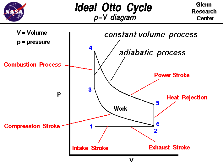
The image below looks complicated, but in reality it simply represents two qualities, pressure and volume, during any stage in an engine's operation. It is called, understandably, a P-V diagram. It characterizes the Otto cycle into six processes, assuming each process occurs in quasi-equilibrium, meaning the changes are occurring slowly enough to call the system "balanced." That's one of many assumptions engineers make, and indicates we pretend things are close to constant so we can use equations to characterize the system.
 |
| Image courtesy of nasa.gov |
Starting at (1), air/fuel is drawn into the cylinder at constant pressure, in scientific terms, isobaric expansion. Once the air/fuel is inducted, it is compressed by the piston (2-3), decreasing the volume and increasing pressure by the Ideal Gas Law. Another assumption is made here; the compression is adiabatic - no heat energy enters or exits the system boundaries during this compression.
| Compression Ratio and Thermal Efficiency: Many gearheads understand that increasing compression ratio generally increases the amount of power generated by an engine, assuming no detonation occurs. What many do not understand is why. Increasing the compression ratio of an engine increases the thermal efficiency of the engine, Thermal efficiency is simply the ratio of energy out to energy in (energy output by the engine / energy released by combustion of fuel.) If you think about it it makes sense. By squishing the intake charge more before it is ignited, you are able to extract more mechanical energy out of the energy generated by combustion.In reality, because compressing the air/fuel increases its temperature, it is possible to make the mixture autoignite or detonate, in which the mixture burns spontaneously without the sparkplug initiating it. While Diesel engines run using this principle, it can cause spontaneous ventilation - by throwing engine parts through your block. |
|---|
After this compression, the fuel is ignited. While this doesn't occur instantly we, again for convenience, assume this energy is added instantly with no time for volume to change. This is called an isochoric process. This sudden increase in temperature in a constant volume creates a pressure spike - which brings the engine from point (3) on the graph to point (4).
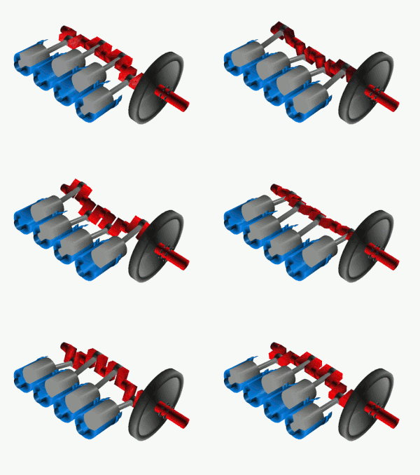
The piston then begins to move because of this additional pressure. This step is where the actual work is done by the system, the power stroke. The piston is pushed downward (adiabatic expansion,) and this force is harnessed by a crankshaft, a shaft that has bearing surfaces on offset axes (see image below.)
Next, in the exhaust stroke, heat is assumed to be rejected isochorically (5-6) and the piston decreases volume isobarically (6-1), indicating the hot gasses have been expelled and conditions have returned to those in step one, and the cycle repeats.
All of this happens thousands of times a second in a modern racing engine. As I've said before, "suck, squish, bang, blow," four little words that succinctly express everything I've said in the few hundred words above. You might think engineers just like to make pretty pictures, but race engineers like to make other things that are pretty too, as the following poor quality video illustrates:
I don't think Otto quite had that in mind when he was playing with pistons in the 19th century. Quasi-equilibrium my left ear.
Next, in the exhaust stroke, heat is assumed to be rejected isochorically (5-6) and the piston decreases volume isobarically (6-1), indicating the hot gasses have been expelled and conditions have returned to those in step one, and the cycle repeats.
 |
| Cylinders (blue,) pistons (grey,) and crankshaft (red.) |
All of this happens thousands of times a second in a modern racing engine. As I've said before, "suck, squish, bang, blow," four little words that succinctly express everything I've said in the few hundred words above. You might think engineers just like to make pretty pictures, but race engineers like to make other things that are pretty too, as the following poor quality video illustrates:
I don't think Otto quite had that in mind when he was playing with pistons in the 19th century. Quasi-equilibrium my left ear.


Great site, nice to see somebody who knows what they are talking about taking the effort to put some truth out there on the interwebs.
ReplyDeleteI think you have you're explanation of engine thermodynamic efficiency upside down though, I would write it as energy output by engine/energy released by combustion of fuel, this way the efficiency is less than 100%
You're absolutely correct! I had the two swapped. It's good to know someone is reading along!
ReplyDelete