| After months of ordering parts from 400 miles away, most of my fuel system parts have come in and now it's a matter of fitting everything together and making sure all the bits and pieces I have are going to work. I imagined and drew diagrams and conjured visions with interpretive dance in an attempt to make everything right the first time. In typical project fashion, I hit a few snags. |
|---|
I liken my project to building a ship in a bottle. Instead of tweezers and a bottle I have wrenches, the internet and a far away garage. I have to build my project in my head before I even pick up my internet tweezers and select a part.
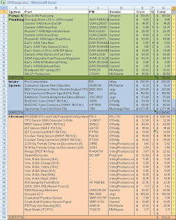
Because I am away from home for near 280 days a year, I added every part I could possibly think of needing on an Excel spreadsheet, complete with part numbers from each vendor, dimensions and connection types in the hopes I could order all the parts for the project before I started work.
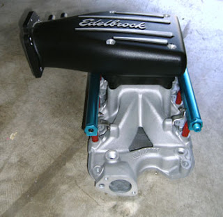
Even with all that forethought, there's that "oh no" moment when I get home and attempt to thread my AN elbow into the fuel pump and realize that the thread pitch was in fact not M12 x 1.25 like Google said, but M12 x 1.5. That's almost as bad as realizing my brain exaggerates packaging space and my intake elbow choice requires me to mount the throttle body partially embedded in the shock tower.
Not quite enough room for the TB. But I'll figure something out.
Nonetheless, the rest of my parts are here, in good shape, and ready to be installed. The very first issue I had to address was the fuel tank. The stock tank on the vintage Mustangs is very simple - no baffles, no sump, just a metal box with a tube in it to suck up fuel. With a carbureted system this is fine. In the event that the driver actually exceeded a tenth of a G of acceleration and the fuel pickup is uncovered, the float bowls of the carburetor hold enough that there's no real loss in fuel delivery. Not only is this unlikely because 1960's tires were almost as bad as 1960's suspension geometry, but everyone was too busy making love and tie-dye or watching Armstrong bunny-hop about on the moon to drive fast.
| Of course if you're awesome you can drive fast while on the moon, where 1G of acceleration is significantly less at 1.6 m/s^2. Even more awesome if you're wearing a tie-dye shirt. |
Here in the post-modern United States decades later we have no manned spacecraft but have racecars that can out-accelerate the now-defunct Shuttle in two axes. Fuel injection systems with an unbaffled tank and no secondary surge tank will lose pressure with even a momentary uncovering of the pickup. At best this will cause power loss and at worse will result in a destructive lean condition of Apollo 13 proportions.
My options were to use the stock tank and integrate a small surge tank fed by a low pressure pump, add a baffled sump to the bottom of the stock tank, or switch to a more modern tank design suited for EFI.
| This fuel cell is a 16 gallon drop-in replacement for an OEM Mustang tank from FuelSafe and has all the benefits of a racing fuel cell while utilizing the stock filling location. |
| Ford says: We are working on that issue. We promise. |
Not only do I want to prevent 16 gallons of fiery death hitting me when a Toyota unintendedly accelerates into my back seat, but I reduce fuel slosh and improve fuel delivery, because racecar. In the event I take the car to a real road race I may still have to add a surge tank to accommodate any high-G sweepers, for now it will be more than sufficient on the road.
The next step is the fuel pump. I am using a Bosch 044 in-line fuel pump. This pump is well known in the fuel injection crowd and flows plenty for my application (another popular pump is the 255lph Walbro.) To be sure it was sufficient I ran a few quick calculations. First I estimated fuel requirements for my motor.
I know my engine makes somewhere in the vicinity of 375 hp from dyno testing, I want to support up to 450 hp for future mods. With a reasonable assumption of the Brake Specific Fuel Consumption (BSFC) at 0.50 lb/hp-hr:
 | |||||||||
| The required volumetric flow rate of the pump can be estimated from fuel density, BSFC, and power numbers |
To get the required fuel to the rail, we have to pump it through lines. These fuel lines induce both wall friction and pressure head loss from the difference in fuel tank and fuel rail elevations. I'm not going to get into the specifics of this calculation (the D'Arcy-Weisbach Equation if you are interested) but you can find an online calculator here. With fifteen feet of 3/8" fuel line the pressure drop is around 2psi. I also estimate my pre-rail 40 micron fuel filter to induce a 2psi pressure drop.
This means the pressure that the pump has to operate at will be 4psi higher than the pressure the injectors see - those extra 4 psi are lost to friction and pressure head. I am also sizing my return line at 3/8." I have a lot of line of this size, and it is better for the return line to be too big than too small - a too-small line can result in pressure on the heated return fuel which can lead to foaming in the tank from insufficient de-aeration as well as pressure fluctuations with sudden changes in throttle position.
Now I need to check the pump I have in mind to see if it flows enough fuel at the operating pressure of my injectors. The injectors are rated at 43.5 psi to 30 lb/hr, so the pump output will be 47.5 psi.
 |
| It's important to note the voltage this test was done at - voltage will affect both pressure/flow ratings and amperage draw. This graph assumes a 14.5V supply. |
 |
| The pump is pretty hefty, but it should be for how much it flows. |
 |
| Bits and pieces. I get these pictures from my brother and get antsy like a kid at Christmas to get home and play with them. |
Electric fuel pumps are very susceptible to damage from dirt and debris, so I am employing a 100 micron pleated stainless pre-filter to keep junk out. This filter as well as all inlet plumbing from fuel cell to pump are -8AN (1/2" ID equivalent) to reduce any suction loss and keep the pump from cavitating. Any cavitation can burn an electric pump up very quickly and also cause an engine-damaging lean condition. Fuel line from the pump outlet is -6AN braided nylon hose to 3/8" hard line to the engine compartment, and back to -6AN line to the filter, rail, regulator, and 3/8" steel return line. I am using steel Bundyweld tubing. I do not recommend using aluminum fuel line even for low pressure systems due to its lack of fatigue resistance and low resistance to highly corrosive modern fuel blends, but I recommend strongly against using it for a high-pressure EFI system.
 |
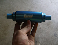
| 100 micron -8AN Pre-filter from Summit |
Lacking the fuel cell to start my fuel system installation, I moved to wiring the ECU. While looking under the dash for a suitable location for the Performance Electronics EDGE ECU, I discovered that my heater core was leaking. Since my heater wasn't functioning anyway and it's summer, I removed the heater box from under the dash until a later date, freeing up a lot of space and pouring a quart of old antifreeze into my carpet. I started the process of segregating wires and running them to their respective locations. I mounted my fuse block and relay bus to the inner fender apron and began labeling and putting everything in place. Once I get everything sorted I will post pictures of my installation and wiring harness progress.
Here's a vid of the car in its current state. Note the terrible low end bog. This is because I can't tune a carburetor and the vacuum signal from this motor at low speed is terrible. I'd probably need annular boosters for it to run right below 3,000 RPM.
This leaves the matter of my throttle body. I'm going to have to devise some method to either adapt my TB elbow or modify the shock tower. Since it's the last component that I have to worry about, I'll think on it while I assemble the rest of my components.
Wish me luck, now starts the fun part!


Do you have hood clearance if you added spacers at the intake?
ReplyDeleteDodge used to make intakes that set their carbs at an angle to the intake. This might be the solution. Fab a spacer that slightly skews the intake mounting configuration.
I have also seen offset spacers used. A machine shop could fab one fairly cheaply, I'd think.
Good luck on a successful install!
Hood clearance is tight but in that pic I have a 1" spacer with room for around 1" more. I've also got some quarter inch sheets of phenolic.
ReplyDeleteThat's a good idea, I considered either a secondary elbow or an adapter to rotate it 5-10 degrees, that may be what I end up doing. I don't mind a little extra plenum volume anyways.
Thanks for the support, it's much appreciated!