
| Since my last update I've done nothing but play with a bird's nest of wires. Bundling, zip-tying, heat shrinking, sheathing, undoing all of that and redoing it again trying to get every wire in its proper place. Also, my fuel cell is here! |
 |
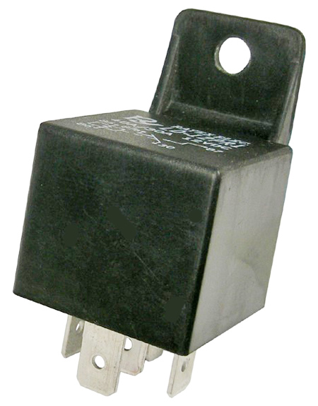
| Starting to get them all connected: Relay bus and fuse block. Fuse block will be below MSD in final setup. |
Well, I've finally started stringing wires and putting relays and fuses together. I've made my relay bus of a fabricated aluminum bracket that will also serve as common ground for all my electronics. When you have multiple systems of different voltages working together that are highly dependent on electrical signals (almost all information is carried as voltage differences) it is critical to keep all the grounds at zero potential to each other.
 |
| The wiring harness by volume is larger than the entire ECU |
 |
| There's a lot of room under the dash without the heater box. |
Wiring is actually one of my favorite (and one of the most therapeutic) parts of a project. The only concentration other than connecting the right bits is making it look neat and keeping the wires safe; you just follow the wiring diagram. I really like the solvent/thermal resistant expandable nylon sheathing. It can cover a far larger range of wire bundle sizes and it looks slick.
 |
| McMaster-Carr carries this expandable mesh sheathing. It works just like a chinese finger trap. |
 | |||||
| Yes, all those wires have a purpose. |
I'm also wiring up my Innovate LC-1 Wideband O2 controller so I can run wideband closed loop control. I also have a narrowband Autometer gauge I will drive with the second output on the LC-1 (the adjustable calibration curves allow you to use the wideband sensor even with a narrowband-only ECU by simulating the response curve of the sensor) so even without a laptop plugged in I can observe AFR in a limited fashion. (I can activate datalogging with a switch or pushbutton if I see anything funky)
That leaves me a lot of options for sensors. I'm planning two thermocouples on the radiator inlet and outlet to plot heat rejection and a set of wheel speed sensors whenever I feel like implementing the ECU's traction control module. This car is going to become a test bed for any technology I am interested in.

Look for the next update soon!
No comments:
Post a Comment